
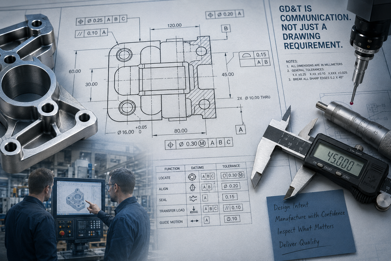
Drawings Alone Do Not Create Alignment
Geometric Dimensioning and Tolerancing (GD&T) is often introduced as a drafting standard tied to manufacturing drawings. In many organizations, GD&T enters the conversation late in development, when drawings are nearing release and inspection requirements must be finalized.
That timing limits the value GD&T can provide.
GD&T functions most effectively as a communication system that aligns design intent across engineering, manufacturing, quality, suppliers, and inspection. It creates a shared understanding around how a product is intended to function, which features matter most, and how much variation the design can accommodate without compromising performance.
When that communication breaks down, the consequences extend well beyond the drawing.
GD&T Defines Functional Relationships
Components locate one another, transfer loads, seal against mating surfaces, guide motion, and maintain alignment across assemblies. GD&T provides a structured method for describing those relationships in measurable terms.
A datum structure defines how a part is intended to orient and interface within the assembly. Position tolerances communicate acceptable variation of critical features relative to those relationships. Profile tolerances establish boundaries for surfaces whose geometry directly influences fit or performance.
Without that clarity, downstream teams must interpret design intent independently. Manufacturing may focus process controls on the wrong features. Quality may build inspection plans around dimensions that are easy to measure instead of those that determine assembly success. Suppliers may interpret ambiguous requirements differently, creating variation between production lots or manufacturing sites.
Technically Correct Drawings Can Still Fail
These problems can occur even when a drawing complies with GD&T standards. Symbols and feature control frames alone do not guarantee that functional intent has been communicated effectively.
The disconnect often begins when GD&T is applied near drawing release, after the product architecture and manufacturing approach have already been established. Tolerances become layered onto a completed design. Datum structures may reflect drawing convenience rather than actual assembly conditions. Requirements may be inherited from legacy drawings without understanding why they were originally created.
The result can be a technically correct drawing that communicates geometry while leaving functional priorities unclear.
The Wrong Tolerance Creates Risk in Either Direction
Poor communication of functional intent can drive tolerances in either direction.
When tolerances are tighter than the product requires, manufacturing may need more capable processes, specialized fixtures, additional inspection, or unnecessary process controls which drive the part cost higher than it should be. Scrap and rework can increase without providing a corresponding improvement in product performance.
When tolerances are too loose, the consequences can be more serious. Excessive variation may affect alignment, sealing, motion, load transfer, assembly, or other characteristics directly tied to product performance. A process can produce parts that satisfy the drawing while still creating problems in the finished product.
The objective is to establish tolerances that accurately represent the functional limits of the design.
This is why GD&T decisions should begin with questions about function. Which surfaces establish alignment? Which features control sealing or motion? Which interfaces determine assembly success? The answers should drive datum selection and tolerance strategy before manufacturing and inspection approaches are locked.
Shared Understanding Improves Product Development
Effective GD&T development requires participation across functions. Manufacturing engineering can identify requirements that create unnecessary process difficulty. Quality engineering can ensure that inspection methods evaluate the features that actually determine product acceptability. Suppliers can identify tolerance strategies that introduce ambiguity or process risk.
These conversations have the greatest value early enough in development to influence the design itself.
When functional relationships are clearly communicated, manufacturing understands what requires close control and where variation is acceptable. Quality understands what must be measured and why. Suppliers have a clearer basis for developing capable processes. Design engineers gain confidence that the product they intended is the product that will actually be produced.
GD&T provides the common language connecting those decisions. Used effectively, it turns functional design intent into requirements that manufacturing can control, quality can verify, and suppliers can consistently execute.
Free GD&T Assessment
A65 Consulting helps product development teams strengthen the connection between design, manufacturing, and quality through practical engineering systems that improve manufacturability, inspection alignment, and cross-functional execution.
If your organization is experiencing recurring drawing interpretation issues, inspection disputes, excessive tolerance complexity, or manufacturability challenges, we would welcome the opportunity to help evaluate the underlying system driving those outcomes.
Email: sdonnigan@a65consulting.com
Or schedule your review online
References
Reinertsen, D. G. (2009). The Principles of Product Development Flow: Second Generation Lean Product Development. Celeritas Publishing.
Ulrich, K. T., & Eppinger, S. D. (2015). Product Design and Development (6th ed.). McGraw-Hill Education.
ASME. (2018). ASME Y14.5-2018 Dimensioning and Tolerancing. American Society of Mechanical Engineers.
ISO. (2017). ISO 1101:2017 Geometrical Product Specifications (GPS) — Geometrical Tolerancing — Tolerances of Form, Orientation, Location and Run-Out. International Organization for Standardization.
Ward, A. C. (2007). Lean Product and Process Development. Lean Enterprise Institute.
Shah, J. J., & Mäntylä, M. (1995). Parametric and Feature-Based CAD/CAM: Concepts, Techniques, and Applications. Wiley-Interscience.
Bralla, J. G. (1999). Design for Manufacturability Handbook (2nd ed.). McGraw-Hill.